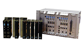
Information and Control Network [TC-net™ 100]
![nformation and Control Network [TC-net™ 100] image](/content/dam/toshiba/migration/infrasolution/www/infrastructure/industrial/assets/san-comp-thum_tc-net.jpg)
The TC-net™ 100 is an information and control network based on the Ethernet, a de-facto standard network, and is available for the message transmission with the use of the TCP/IP and the UDP/IP.
The TC-net™ 100 is an information and control network based on the Ethernet, a de-facto standard network, and is available for the message transmission with the use of the TCP/IP and the UDP/IP.
The TC-net™ 100, maintaining the openness of the Ethernet, is ready to interconnect seamlessly between information and control, and further is capable to extend to the internet and/or the intranet.
The TC-net™ 100 is an information and control network conforming to the IEC/PAS (Publicly Available Specification) 62406 Real-Time Ethernet TCnet (Time-critical Control Network) approved by the IEC.
The TC-net™ 100 is based on the communication technology of the TCnet, which is one of the Real-Time Ethernet under standardization in the working group of the IEC/TC65/SC65C and is proposed
by the Japan national committee.
General
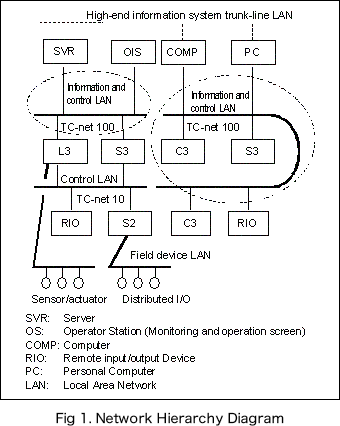
As shown in Figure 1, the network of the Integrated Controller V Series is based on a hierarchical configuration.
TC-net™ 100 realizes high-speed and real-time transmission between supervisory units, computers and controllers
via the Information and control LANs indicated by dotted lines in Figure 1.
Features
TC-net™ 100 has the following features.
Openness
This network for monitoring and control maintains the openness of the 100Mbps Ethernet and has the collision avoidance function and the definite time responsiveness.
Communication service
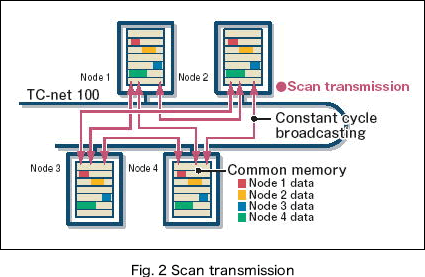
The communication service includes the scan transmission which transmits control data periodically (cyclic broadcast reception/transmission) and the normal message transmission.
- Scan transmission involves three speed modes, that is, high speed, medium speed and low speed, which can be allocated in accordance with the data update cycle, thus securing definite real-time responsiveness.
- In message transmission, the network has realized the protocol compatibility between TOSDIC™-CIE 1200 and T3H, supported not only by TCP/UDP/IP but also by Toshiba Standard Protocol and PCMP.
[Note]
PCMP is abbreviated from Process Control Message Protocol.
High reliability
Can construct a highly reliable system configuration through transmission path dualization. The transmission path can select either Optical or Electrical.
Network relay function (Scheduled)
TC-net™ 100 can relay message transmissions directly between TC-net™ 100 or Ethernet and transmission modules of another system.
Securing control data synchronism
A control system must meet the requirement for data synchronization between each node.
The TC-net™ 100 secures control data synchronization by scan data transmission with so-called common memory system. The scan data transmission,
based on cyclic transmission, is available at any of three speeds (hight, medium, low) whitch may be selected ranging from 1 ms second minimum in units of 0.1 m second, an impossibility with the conventional Fast Ethernet.
The TC-net™ 100 is free of delays in control data transmission even in the case where a large volume of data, for example, of moving pictures, is transmitted.
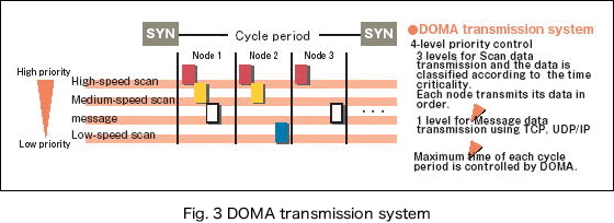
High-performance transmission
- The conventional Ethernet technology is subject to serious ill effect on the response time in the presence of a data collision, in the case of multiple broadcast communications at one time, on the transmission medium.
- The TC-net™ 100 employs the DOMA (Deterministic Orderd Multiple Access) transmission scheduling, to eliminate data collision and ensure deterministic, high-response data transmission for wide variety of time-critical industrial applications.
Network Configuration
Transmission module
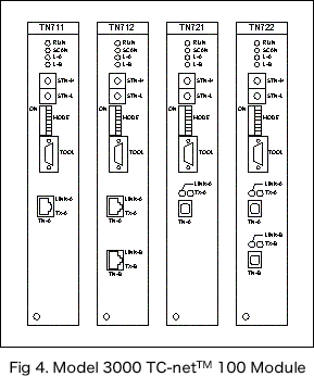
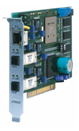
TC-net™ 100's transmission modules are available in eight types as listed in Table 1.
List 1 Types of Transmission Modules
This table can be scrolled horizontally.
| Module name | Description | |
|---|---|---|
| For model 3000 | TN711 | Single electric transmission path |
| TN712 | Double electric transmission path | |
| TN721 | Single optical transmission path | |
| TN722 | Double optical transmission path | |
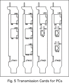
| For PC | JTNI11 | Single electric transmission path |
| JTNI12 | Double electric transmission path | |
| JTNI21 | Single optical transmission path | |
| JTNI22 | Double optical transmission path | |
| For TOSLINE-8000 | TNGW-5652 | Double optical transmission path |
Mounting configuration
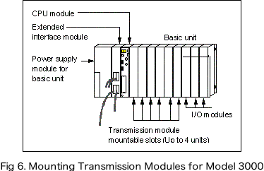
The model 3000 transmission module is mounted on the station bus slot of model 3000's controller basic base. Up to four transmission modules can be installed in the basic base (Figure 6).
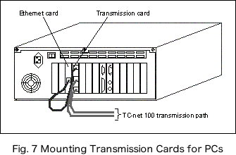
The transmission card for PCs is installed in the PCI bus slot of the PC.
The general-purpose Ethernet card is also installed for message transmission.
The transmission card for PCs and the general-purpose Ethernet card
are connected to each other via the attached twisted-pair cable. Up to two transmission cards can be installed in the PCI bus slot (Figure 7).
TOSLINE-8000 Gateway station
The TOSLINE-8000 Gateway station is the network interconnection device between the TOSLINE-8000 and the TC-net™ 100.
On the TOSLINE-8000 side, the SVC station and the local station which controls the input/output data from/to
the field devices, are connected by using the fiber optic cable.
On the other TC-net™ 100 side, the TC-net™ 100 stations such as the integrated controller V series with the TC-net™ 100 model 3000 module and the personal
computer with the TC-net™ 100 PCI bus interface card, are connected by using the redundant fiber media. The TOSLINE-8000 Gateway station is restricted to intercommunicate the scan data between the TOSLINE-8000 and the TC-net™
100.
Transmission path components
List 2 Types of Transmission Path Components
This table can be scrolled horizontally.
| Module name | Description | |
|---|---|---|
| Optical shared hub | UTNH21A | For transmission path line-A |
| UTNH21B | For transmission path line-B |
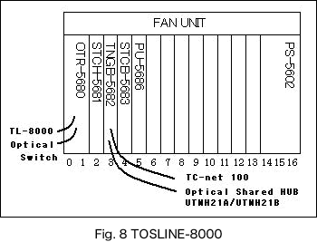
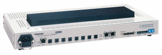
Optical shared hub is required to configure TC-net™ 100's optical transmission path (Figure 9).
The optical shared hubs are available for the Line A and the Line B. And when the transmission path is dualized, these lines are connected to the respective paths.
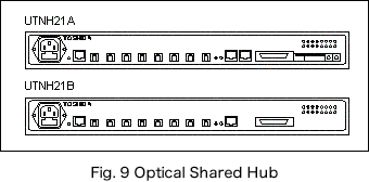
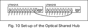
Figure 10 shows the set-up of the optical shared hub in case of the redundant media configuration.
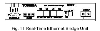
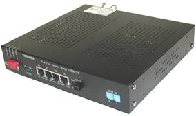
Real-Time Ethernet Bridge Unit
The Real-time Ethernet bridge is the intermediate device for seamless connection between the segments of the TC-net™ 100 Real-Time Ethernet and the general purpose Ethernet, and by using the Real-Time Ethernet bridge a variety of the Ethernet devices is able to hook up to the TC-net™ 100.
Transmission specifications & module specifications
General specifications are in accordance with the controller.
List 3 Transmission Specifications
This table can be scrolled horizontally.
| Parameter | Description | |
|---|---|---|
| Data transmission speed | 100Mbps | |
| Medium access | DOMA (Deterministic Ordered Multiple Access | |
| Topology | Star (Transmission path dualizable) | |
| Transmission cable length | Maximum length between nodes: 8 km Optical fiber: 2km (Note 1) Twisted pair cable: 100 m |
|
| Number of hub cascades | 3 cascades | |
| Number of nodes | Up to 254 nodes per system (Note 2) | |
| Transmission mode | Scan transmission High-speed scan period: 1 ms to 160 ms Medium-speed scan period: 10 ms to 1,000 ms Low-speed scan period: 100 ms to 10,000 ms Message transmission TCP/IP system message reception/transmission |
|
| Scan transmission capacity | 128KW per system (16 bits per word) 2048 blocks per system (64 words per block) Transmission capacity 576 blocks per node (36KW per node) Status change detection (Note 3) Change detection word count: 128 words per node Change detection cycle Change detection word count 30 s Detection signal interval: At least 50 ms |
|
| Cable | Electrical | Category 5 twisted-pair cable |
| Optical | Quartz GI cable (62.5/125; long wavelength) or (50/125; long wavelength) | |
| Connector | Electrical | RJ-45 modular jack |
| Optical | MT-RJ type optical connector | |
| Grounding | Class D (Grounding resistance : 100 ohms or less) | |
- [Notes 1]
If laser emission diodes and optical fiber single mode are used, up to 8 km can be extended. (Under development) - [Notes 2]
Optical shared hubs (UTNH21A) are also included in the station count. - [Notes 3]
Some product types are unsupported.
List 4 Model 3000 Module Specifications
This table can be scrolled horizontally.
| Parameter | Description |
|---|---|
| Connected device | Integrated controller |
| Connected bus | Station bus |
| Slot occupied | One slot per module |
| Number of modules mounted | Up to four modules per controller basic unit |
| Transmission path dualization | Available |
| Current consumption | 2A or less |
| Tool connection | D-Sub 9 pins (Male) RS-232C connection |
List 5 PC Card Specifications
This table can be scrolled horizontally.
| Parameter | Description |
|---|---|
| Connected device | Personal computer |
| Connected bus | PCI bus |
| Slot occupied | One slot per module As other, an Ethernet card is required |
| Size | Half size |
| Number of modules mounted | Up to two cards per PC |
| Transmission path dualization | Available |
| Current consumption | 2A or less |
List 6 Optical Shared Hub Specifications
This table can be scrolled horizontally.
| Parameter | Description |
|---|---|
| Port count | Optical: Eight ports Electrical: One port |
| Tool connection | RJ-45 modular jack 100M Ethernet connection |
| Supply voltage | 95 to 250V, 50/60 Hz |
| Current consumption | 100Vac; 60W or less |
| Operating temperature range | 0 to 55 degree C |
| Appearance | 446mm(W) x 45(H) x 221.5(D) |
| Weight | 5kg or less |
List 7 Ethernet Bridge
This table can be scrolled horizontally.
| Parameter | Description |
|---|---|
| Port count | TC-net™ 100 Optical: One ports Ethernet Electrical: Four ports |
| Supply voltage | 85 to 264V, 50/60 Hz |
| Current consumption | 100Vac; 20W or less |
| Operating temperature range | 0 to 55 degree C |
| Appearance | 220mm(W) x 40(H) x 205(D) |
| Weight | 1.2kg or less |
- Ethernet is a registered trademark of Fuji Xerox Co., Ltd. in Japan.
- TC-net, TOSDIC are registered trademarks of Toshiba Corporation.
- Other company names and product names herein are trademarks or registered trademarks of the companies concerned.
* The contents are subject to change without notice for design changes or other reasons.