Engineering Tool
The engineering tool supports all the phases of a V-series system from system configuration to programming, monitoring RAS information collection, and monitoring.
Information
The execution environment of the Engineering Tool was improved.
Microsoft® Windows® 7 (Professional / Ultimate)
The fixed the Engineering Tool version is following.
- Synchro Trend V1.3.0
- Permissive Fault Diagnosis V1.4.0
- New Instrument FB Library (DS) V1.2.0
Microsoft® Windows® Server 2008 SP1/SP2
The fixed the Add-in software version is following.
- Engineering tool 3(V-Tool3) V3.13.0
- Engineering tool 2(V-Tool2) V2.17.0
- Synchro Trend V1.1.0
- Permissive Fault Diagnosis V1.2.0
- New Instrument FB Library (DS) V1.1.0
- New Instrument Tag Editor V1.5.0
Microsoft® Windows Vista®
Microsoft® Windows® XP SP3
The fixed the Engineering Tool version is following.
- Engineering tool 3(V-Tool3) V3.11.0
- Engineering tool 2(V-Tool2) V2.15.0
- Synchro Trend V1.1.0
- Permissive Fault Diagnosis V1.2.0
- New Instrument FB Library (DS) V1.1.0
- New Instrument Tag Editor V1.5.0
[Note]
- In PC in which Windows Vista® is installed, when the Engineering Tool are installed for the first time, it is necessary to use CD of the above-mentioned version and to install it.
- Update file of the Engineering Tool cannot be newly installed in Windows Vista®.
- Please obtain the CD from Toshiba corporation without CD of the Engineering Tool.
PC that installed Microsoft® Office 2007 or Microsoft® Office OneNote® 2007.
PC that installed Microsoft® Office 2003 SP3 or Microsoft® Office OneNote® 2003 SP3.
The fixed the Engineering Tool version is following.
- Engineering tool 3(V-Tool3) V3.7.0
- Engineering tool 2(V-Tool2) V2.12.1
[Note]
Please confirm the following if the error occurs when the station, the unit, and the module, etc. are added with the Engineering Tool.
- The version and service pack of Microsoft® Office.
- The version and service pack of Microsoft® Office OneNote®.
- The version of the Engineering Tool.
Engineering tool 2 / Engineering tool 3
Successor to the existing Integrated Controller engineering tool, version 2 and version 3 features improved user interface, added ease of operation, and higher engineering efficiency through reducing program save time.
Engineering tool 2 and Engineering tool 3 will fully justify the true value of the Integrated Controller V series.
The Engineering tool 3 supports full-graphic editor and ST language (Structured Text) editor in addition to all the features of the Engineering tool 2.
Click image to enlarge
Integrated engineering
The engineering tools for the V series assure integrated engineering regardless of system size and control functions (sequence, instrumentation). The S and L modules can be programmed in the same program language. Apart from programming, hierarchical engineering is available from system to controller, involving network and hardware configuration and module parameter setting.
Click image to enlarge
Integrated engineering
The V series conforms to the international standard IEC61131-3 for its programming languages. The three graphical languages LD (Ladder Diagram), SFC (Sequential Function Chart), and FBD (Function Block Diagram) can be mixedly used on a single campus , thus permitting programming along the control flow.
A program can be created function by function, and a common function can be defined as a function block. This makes possible hierarchical programming.
Click image to enlarge
Free variables
The local variables that can be used in a program can be defined without being conscious of data physical addresses, and the same variable name can be defined in two or more programs.
The global variables that can be used in common in two or more programs are of a hierarchical structure involving not only the variables usable in common in modules but also the variables that can be used in common between station modules and the variables usable in common between networks, so that data can be exchanged without being aware of system size.
Click image to enlarge
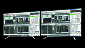
Effective also for system maintenance
The engineering tool is effective for not only program monitoring, data value display, setting, trace, module status monitor and operation, module history display and other programming operations and system configuration but also for maintenance, thus permitting integrated engineering with a single engineering tool.
Click image to enlarge
Click image to enlarge
Reverse creation function restores and builds a system from controllers
Programs, variables, hardware configuration, and other information can be fetched from the controller by the engineering tool to restore and build a system. (*1) This reverse creation function facilitates controller maintenance without program and other data in the field.
- *1 In downloading data to the controller, download the data necessary for the reverse creation function. Memory consumption by the controller is greater than the actual program capacity in using this function. This function applies only to the sequence control modules S2 and S3.
Group engineering by client/server
The engineering tool may be used not only singly but also in client/server mode. This makes possible the centralized control of data by a server machine and parallel engineering with two or more client machines. This feature is effective for exclusive processing in competitive operations in which two or more clients may simultaneously edit and compile a program, thus assuring efficient group engineering.
Waste-free transition of engineering data
(Engineering tool 2 / Engineering tool 3)
variables and other engineering data can be used by converting them into data for the engineering tool 2 and engineering tool 3, using V1 Import, which is a standard component of the engineering tool 2 and engineering tool 3. Therefore, the data created so far can be shifted to the engineering tool 2 and engineering tool 3 without waste.
Operating conditions
Engineering tool 3 List
This table can be scrolled horizontally.
| Hardware | Windows® 2000/Windows NT®4.0: PC/ATcompatible machines: Intel Pentium® 400 MHz or higher (server: Pentium® III 1 GHz or higher) Windows® XP: PC/ATcompatible machines: Intel Pentium® III 1 GHz or higher (server: Pentium® 4 1.7 GHz or higher) Windows Vista®: PC/ATcompatible machines: Intel® Core™2 1GHz or higher (server: Core™2 2GHz or higher) Windows Server® 2003 R2, 2008 SP1/SP2: PC/ATcompatible machines: Intel® Xeon® 3GHz or higher / Intel® Core™2 2GHz or higher |
|---|---|
| OS | Microsoft® Windows® XP (SP1 and up)/Windows®2000 (SP3 and up)/Windows NT® 4.0 (SP6a and up) Microsoft® Windows Vista® Business SP1 Microsoft® Windows Vista® Ultimate SP1 Microsoft® Windows Server® 2003 R2 Enterprise Edition SP2 * V3.11.0 and newer versions are compatible with Windows Vista®. Microsoft® Windows® Server 2008 SP1/SP2 |
| Memory | Windows® 2000/Windows NT®4.0: 128 megabytes or higher (server: 256 megabytes or higher) Windows® XP 384 megabytes or higher (server: 512 megabytes or higher) Windows Vista®/Windows Server® 2003 R2/Windows® Server 2008 SP1/SP2: 1gigabytes or higher |
| CD-ROM drive | Necessary for setup |
| Interface | RS-232C/RS485/Ethernet |
Engineering tool 2 List
This table can be scrolled horizontally.
| Hardware | Windows® 2000/Windows NT®4.0: PC/ATcompatible machines: Intel Pentium® 400 MHz or higher (server: Pentium® III 1 GHz or higher) Windows® XP: PC/ATcompatible machines: Intel Pentium® III 1 GHz or higher (server: Pentium® 4 1.7 GHz or higher) Windows Vista®: PC/ATcompatible machines: Intel® Core™2 1GHz or higher (server: Core™2 2GHz or higher) Windows Server® 2003 R2, 2008 SP1/SP2: PC/ATcompatible machines: Intel® Xeon® 3GHz or higher / Intel® Core™2 2GHz or higher |
|---|---|
| OS | Microsoft® Windows® XP (SP1 and up)/Windows®2000 (SP3 and up)/Windows NT® 4.0 (SP6a and up) * V2.4.0 and newer versions are compatible with Windows® XP V2.40 Microsoft® Windows Vista® Business SP1 Microsoft® Windows Vista® Ultimate SP1 * V2.15.0 and newer versions are compatible with Windows Vista®. Microsoft® Windows Server® 2003 R2 Enterprise Edition SP2 Microsoft® Windows® Server 2008 SP1/SP2 |
| Memory | Windows® 2000/Windows NT®4.0: 128 megabytes or higher (server: 256 megabytes or higher) Windows® XP 384 megabytes or higher (server: 512 megabytes or higher) Windows Vista®/Windows Server® 2003 R2/Windows® Server 2008 SP1/SP2: 1gigabytes or higher |
| CD-ROM drive | Necessary for setup |
| Interface | RS-232C/RS485/Ethernet |
Newest Version
Engineering tool 2 List
This table can be scrolled horizontally.
| Type Version | Version |
|---|---|
| Standalone (English) | 2.17.1 |
| Client/server (English) | 2.17.1 |
Engineering tool 3 List
This table can be scrolled horizontally.
| Type Version | Version |
|---|---|
| Standalone (English) | 3.13.1 |
| Client/server (English) | 3.13.1 |
- Microsoft®, Windows®, Windows NT®, Windows Vista® and Windows Server®are either registered trademarks or trademarks of Microsoft Corporation of the United States and/or other countries.
- The formal name of Windows® is Microsoft® Windows® Operating System.
- Pentium is a registered trademark of Intel Corporation of the United States in the U.S.A. and other countries.
- Other company names and product names herein are trademarks or registered trademarks of the companies concerned.
* The contents are subject to change without notice for design changes or other reasons.