Electromagnetic
Flowmeter GF630/LF620
GF632/LF622

Electromagnetic Flowmeter (PDF)

GF630/LF620 (Combined type) image. LF622 & GF632 (Separate type) image.
FM(C US) APPROVED image. Certification No. Z01207 image. NSF Certification No.PM09896 For PU lined flowmeter image.

General Specificaition

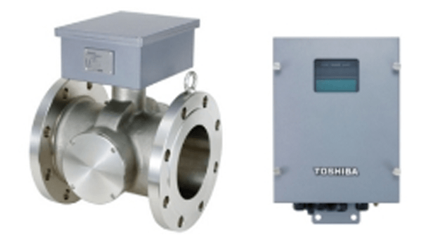
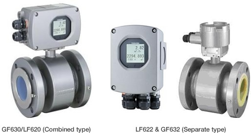
Combined with a multi-functional converter LF620 (Combined type) or LF622 (Separate type) equipped with its original Noise-suppression Circuit& Advanced Algorithms,The GF630 has a very high tolerance to noise, giving the unit a very stable output even for slurry fluid measurement.

The AF900 Hand-held terminal (HART(*1) Communicator) can be used for remote control. PROFIBUS-PA(*2) or Modbus(*3) interface is available as an option.

  • *1 HART protocol (Highway Addressable Remote Transducer) is a communication protocol for industrial sensors recommended by the HCF (HART Communication Foundation).
  • *2 PROFIBUS is the communication protocol for factory automation and process automation that the PROFIBUS Organization recommends.
    Instead of analog control with a conventional analog signal (4-20mA), it is one kind of the fieldbus which digitizes all signals.
    Flowmeters support PROFIBUS-PA.
  • *3 Modbus is the communication protocol that Modicon Inc. developed. Physical layer is RS485

Main Specifications

Main Specifications List

This table can be scrolled horizontally.

Main Specifications List
Mounting style Flange connection type
Meter size 15mm, 25mm, 32mm, 40mm, 50mm, 65mm, 80mm, 100mm, 150mm, 200mm, 250mm, 300mm, 350mm, 400mm, 450mm, 500mm, 600mm
Measuring range in terms of flow velocity 0-0.3m/s to 0-10m/s (0-0.1m/s to 0-0.3m/s as option)
Accuracy
< 1/2" to 18h (15 mm to 450 mm) >
+/-0.2 % of Rate
* This pulse output error result is established under standard operating conditions at Toshiba's admitted flow calibration facility.
* Individual meter measurement error may vary up to +/-0.5% of Rate at 1.64 ft/s (0.5m/s) or more. Or it may vary up to +/-0.3% of rate +/-0.039 inch/s (1mm/s) at 1.64 ft/s (0.5m/s) or less.
* Current output: plus +/-8μA (0.05% of span).
* Refer to individual calibration data for each individual meter's measurement error.
< 20" and 24h (500 mm and 600 mm) >
+/-0.3 % of Rate
* This pulse output error result is established under standard operating conditions at Toshiba's flow calibration facility, Fuchu Japan.
* Individual meter measurement error may vary up to +/-0.5% of Rate at 3.28 ft/s (1.0 m/s) or more. Or it may vary up to +/-0.3% of rate +/-0.079 inch/s (2 mm/s) at 3.28 ft/s (1.0 m/s) or less.
* Current output: plus +/- 8μA (0.05% of span).
* Refer to individual calibration data for each individual meter's measurement error.
Lining materials
(Meter size: mm)
FEP: 15 to 250mm
PTFE: 300 to 600mm
Polyurethane (PU): 15 to 450mm
Fluid temperature -20 to +110℃ (FEP)
-20 to +120℃ (PTFE)
-20 to +60℃ (Polyurethane)
Electrode materials SUS316L (for PU)
Hastelloy C (for FEP,PTFE lining)
Grounding ring materials PU,FEP lining:
None (Standard) SUS316 (Option)
PTFE lining: SUS316 (Standard)
Ambient tempearture -20 to +60℃
Structure IP67
Power consumption 10W (14VA) at AC100V and Excitation current: 0.2A
Power supply AC100V to AC240V, 50/60Hz (Standard) Allowable voltage AC80V to AC264V
DC24V (Option) Allowable voltage DC18V to DC36V
DC110V (Option) Allowable voltage DC90V to DC130V